Cimatron 2025 offers tools across the suite for greater productivity and profitability of customers worldwide.
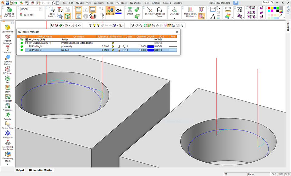
Download BrochureCimatron 2025 now uses a new extension type for CAM 3X profiles to avoid entering and exiting a profile at the same point, and risk leaving a tool mark at that location. The enhanced Extensions are None, Line, Arc, Natural for tool Approach and Retract.
CAM-3X is also enhanced with one procedure for both Open and Closed contours, circular motion on holes and bosses for helical profiles; automated drill reliability; better toolpath quality at corners and at bottom of vertical walls, more reliable chamfer toolpaths, and improved 3X deburring.
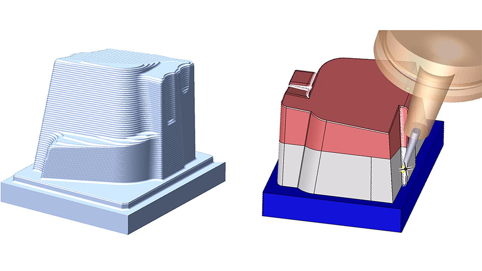
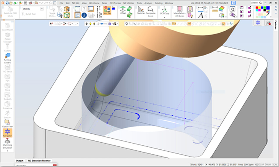
For 5-axis machining, the software now allows the automatic use of remaining stock from previous 3-axis operations during roughing and updates the remaining stock. This enables the use of shorter cutters for greater stability and safe machining.
A wide array of enhancement to CAM-5X functions includes: 5X Auto Tilt taper and lollipop cutters; improved 5X Auto Tilt quality; MX Undercut machine only and rest roughing thickness detection; MX Wall/Floor finishing; MX Rest finishing with new modes for containing toolpath on walls and floors; new MX default Lead-In/Out options; Geodesic cutter control for small hole and big holes; and MX Deburring auto tilt clearances.
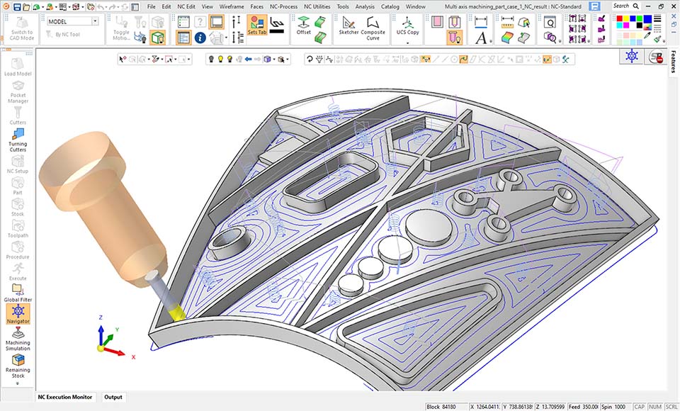
Multi Axis Machining has new 5X procedures which supports circle segment cutters (lens, barrel) with tool axis control (tilt) with user defined Lead/Lag. The new multi-axis procedures support Rough, Floor Finishing, Wall Finishing, and Rest Finishing.
The rough layers (including intermediate down-steps) may be defined by Offset from a single Floor surface, Offset from a single Ceiling surface, and Morph between Ceiling and Floor surfaces. Tool orientation is normal to the Floor surface. Stock considers the previous stock (from v2024) and updates the remaining stock.
Undercut conditions supported are: Do Not Machine, Machine, and Machine Only. Rest Roughing is based on Previous Flat, Bull or Ball Cutters.
Multi Edit of Procedure Parameters now includes Viewing, Editing, and Mass-Editing of multiple procedure parameters. Users can edit a single cell, multiple cells, or an entire column for parameters such as cutter, color, pen width or coolant.
More than 25 important parameters are editable including Tolerance, Offset, Down Step, Side Step, and Machining. Users choose the parameters and order to display, and Save/Load the configuration they prefer.
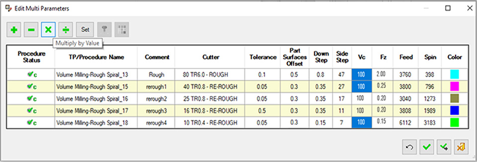
Process Manager now have more column options available for display. In v2025, more parameters (i.e., columns) are available in the Process Manager including Part Offset, Tolerance, Down Step, Sidestep, Feed, Spin, Fz, Vc., Coolant, Electrode Spark Gap, 2D Orbit.
Users control which parameter to display and their order using a column chooser. Save and Load the Process Manager Columns configurations is also enabled.

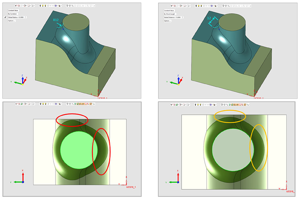
In v2025, the size of a Round can now be defined by Constant Chord Length. Rather than entering the radius value, users can input a value for chordal distance across the round to control its size.
Chord length rounds are still defined by an arc section with a variable radius measurement that is dependent on the relative geometry feature. Like any other round, chord length rounds remain tangential (C1) to the neighboring faces.
In some geometrical areas, a round made with a constant chord length will be provide a more uniform and less stressful shape, often preferred for Die design.
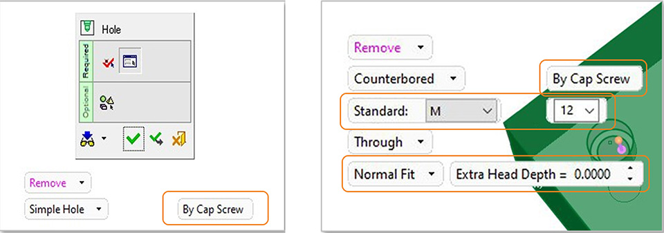
In v2025 it is now possible to define a threaded hole by a selected screw specific size. Holes can be defined by two options, By Dimension (as before), By Cap Screw. The new capability applies to all the existing types of holes, Simple Hole, Counter-Bored, Counter-Sunk and Counter-Drilled.
Seven thread catalogs are currently supported for Hole by Cap Screw, M, M(F), UNC, UNF, NPT, G, and R. Simple Hole that is defined by Cap Screw will be sized by the appropriate tap drill, may include a thread, can set the Delta (depth) by a multiplication factor of the diameter. Counterbored, Countersunk, or Counter-Drilled holes defined by Cap Screw will be sized by the known clear drill, counterbore, and taper angle dimensions and support Normal, Close, or Loose fits.
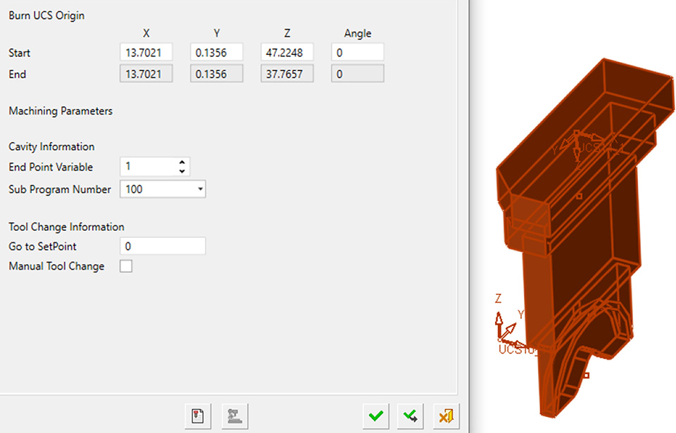
In v2025, the user can Save Electrode or Location values as a Template. The user can then load the relevant template to automatically populate all of the EDM fields. This eliminates the repetitive, error-prone task for EDM machine operators of entering the data for each Electrode and each Location.
The Symbolic Text mechanism enables data from attributes to be presented as PMI or added to a drawing. All the Part and Electrode parameters that are available through the EDM Setup application can be used as Symbolic Text. Location Parameters are also available for Symbolic Texts, making creation of burning location drawings faster.
In v2025, Hole Dimension is a new dimension type that describes the full geometry of a hole. Hole Dimensions use labels and symbols that are fully supported by common drafting standards like ISO, ANSI, and JIS. The modeling-based hole knowledge that contributes data to a table of holes is used to build a hole dimension.
The Hole Dimension feature recognizes and displays the quantity of similar holes. Each hole segment gets its own line in the dimension that can fully describe the diameter and depth information. Threads are listed on a separate line. The look of a Hole dimension can be controlled and customized from the dimension feature guide.


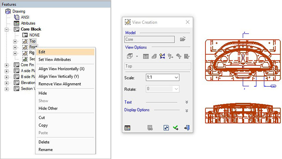
In v2025, the drawing tree now allows for selection of multiple views, making many common drafting tasks easier. The available actions on multi-selected views can be accessed by clicking the right mouse button.
Most View maintenance activities are allowed on multi-selected views, including Hide/Show, Rename, Delete, Align, and Move to different sheets. Most view edits can be performed on multi-selected views including Editing View scale, Show/Hide PMI, Position of view names and Changing view attribute display.
Follow us on